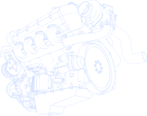
Every engine we make or work on relies on a few core components that do the heavy lifting; the connecting rod sits right in the middle of that. It’s the main link that connects the vital parts. In the pursuit to achieve maximum performance from an engine, we need to study the design of these parts in detail, along with their specific functions in the assembly.
A connecting rod forms the mechanical interface between the piston and crankshaft. The basic function of the engine system is to transform the piston’s reciprocal motion into the crankshaft’s rotating motion. Thus turning the power of combustion into torque.
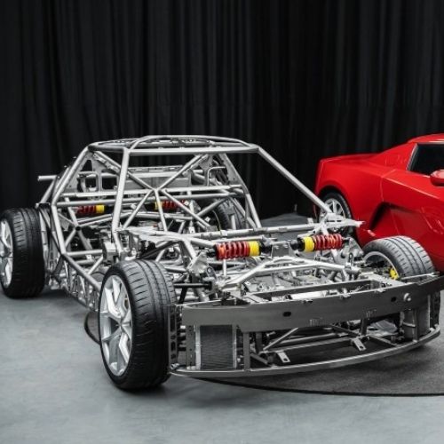
The part is engineered with a small end for the piston pin and a large end that wraps around the crank journal to cater to this. The structural integrity of this component, because it is subjected to high-pressure loading and high-speed inertia hundreds of millions of times, is a primary contributor to engine durability.

Shank is the main body of the rod, having an I-beam or H-beam section to give maximum strength for minimum weight. It withstands the massive compressive and tensile loads experienced during the combustion cycle.
The small end of this sleeve is pressed in so that a low-friction surface is present for the wrist pin. The bearings are used to minimize wear at the pivot where the rod meets the piston assembly.
The small end of the connecting rod has a smaller diameter upper opening connecting with the piston by using a pin. The piston receives a side motion without rotation thanks to the wrist pin connection.
That big end pocket is where the crankshaft bears. The larger split opening at the bottom of the connecting rod. It must be manufactured with great precision to accommodate the bearings and ensure perfect circularity during high speeds.
Although it is a distinct part technically, the piston functions as a pressure-receiving cap that transfers the force into the rod. The energy from the expanding gases captured pushes the rods down to commence the power stroke.
These high-tensile fasteners secure the bearing cap to the connecting rod’s big end. You need the right springs to maintain the correct clamping force to ensure the assembly does not pull apart with inertial loads at high RPM.
Inside the big end are replaceable precision shells that protect the crankshaft from direct metal-on-metal contact. They are made to accommodate oil film lubrication and to take in little wear over time.
Also known as a gudgeon pin, this forged steel piece is locked to the piston when it passes through the small end. The alternating forces of the driver-driven piston’s travel must be quite a tough job.
The bearing cap refers to the lower half, or bottom part, of the big end, which you can remove to install the rod onto the crankshaft. The assembly design is used in the crank pin and is bolted together to provide housing for the connecting rod bearing and to keep the rod fixed to the crank journal.

The high strength-to-weight ratio of this design’s web and thick flanges helps it resist vertical loads. This geometry is employed in production engines, since it channels the tensile forces created during high-speed operations, without creating excessive mass in the rotating assembly.
By reducing the reciprocating weight, these rods minimize the inertial stress placed on the crankshaft journals at high RPMs. The best option for engines for which fast response and low fuel consumption take precedence over withstanding high cylinder pressures.
H-Beam rods employ a parallel-sided architecture, which creates a significantly higher section modulus than the I-beam type. The design overcomes the high compressive forces and sideways bending of turbocharged or high-torque industrial application loads.
With increased material on the outer edges, the rod gets the structural stiffness it needs to avoid “panting” due to high-loading combustion. The H-beam is heavier than other profiles, but also the industry standard to ensure durability in high-stress and high-horsepower applications.
The X-Beam rods are cross-shaped to distribute mechanical stress evenly throughout the body of the component. The hybrid shape resists bending and torsion in all directions. It combines the rigidity of an H-beam with reduced weight.
This setup is generally used in certain race applications or high-output builds that must mitigate complex harmonics and peak acceleration cycles. The X-beam is designed to allow for superior strength in applications where the engine is being operated to the absolute limit of its mechanical capabilities through the optimization of material placement.

The piston connects to a crankshaft with the help of a connecting rod. Thus, a major portion of the combustion energy is conveyed to the crankshaft through a connecting rod. It must be able to withstand high axial loads in the power stroke so that all the cylinder pressure is transmitted through the drivetrain.
The crankshaft converts the piston’s linear movement into the rotational motion of the crankshaft in an internal combustion engine. When this transition is facilitated, the function of the connecting rod is what ultimately allows the engine to produce usable torque at the wheels.
Rods with adequate dimensions permit the piston to approach upper dead center and lower dead center at proper intervals for combustion. These parts must also have balanced weights, so that they can help cancel out the vibration and keep the rotating assembly balanced at high speeds.
The design of the rod allows it to absorb and distribute the huge inertial forces generated by the change of direction of the piston at the top of the stroke. The lifecycle of an engine sees a constant cycle of tension and compression millions of times. It can lead to mechanical failure, and its prevention is critical.
An optimized connecting rod in an engine design increases the internal friction and reduces the reciprocating mass of the engine assembly. Hence, the energy required to move the engine assembly is reduced. The electronic engine control improves the mechanical efficiency of the engine.
Higher mechanical efficiency results in higher power density. It helps in lowering the fuel consumption of the engine. Or we can say, electronic engine control maximizes the output per combustion cycle.

Steel alloys, specifically 4340 forged chromoly, are used for their high fatigue strength, which can withstand millions of cycles of stress. This material is still the industry standard for most applications, due to its predictable expansion rate and outstanding resistance to tensile failure.
By using an aluminum rod, the reciprocating mass is reduced to such an extent that the engine can achieve high RPMs much quicker while putting less load on the crank. Though they do a better job handling heavy shock loads in high-torque racing applications, they usually need more frequent inspection and replacement than steel because of corrosion and shorter fatigue life.
Titanium alloys have the structural strength of steel, yet at a weight profile similar to aluminum, making them ideal engineering materials for high performance. They are relatively resistant to heat and corrosion, but are too expensive and need specialized machining, so they are only used in top-level race or exotic production engines.
The process of powder metallurgy, compressing the granules of metal or metals and sintering them, creates rods that are equally weighted and have near-net shapes. This process is ideal for mass production. The big end is “fracture-split” to guarantee perfect cap alignment and optimum bearing support in typical passenger vehicles.

The process of die casting entails forcing a molten metal into a mold cavity under high pressure to obtain a near-net shape component. This method is cost-effective for mass manufacturing. However, this approach is rarely used for high-end performance rods. This is due to the possible risk of internal porosity. The structural density is also less compared to other methods.
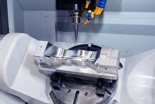
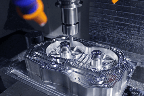
Billet rods are made directly from a solid block of high-grade alloy steel or aluminum with precision computer milling. This method of manufacture can produce perfectly specialized geometries with a very consistent grain structure, making it very useful for prototypes and specially constructed racing engines.
This refers to the process of shaping metal using high temperature and pressure. Forging is done to make stronger and tougher metal parts. It utilizes tremendous heat and compressive force to shape the metal. The process aligns the internal grain structure with the profiles of the connecting rod. The results of this mechanical refinement render a part that has better impact resistance and better fatigue strength.
Combining powder forging with a final forging step creates a part matched with weight tolerances and pores, density, and structure. This process yields an exceptionally consistent part that requires little final machining, providing a high-volume approach and an overall improved structure for new production engines.

The primary determinant of piston dwell time and side-wall friction at the top of the cylinders is the rod-to-stroke ratio of between 1.5:1 and 1.8:1. The longer the length, the lower the maximum rod angle, decreasing the lateral thrust loads acting on the cylinder walls. However, it requires a taller deck height and increases the reciprocating mass of the assembly.
It is important for the designers to balance the rotating mass of the “big end” and the reciprocating mass of the “small end”. By doing so, it is possible to control the primary and secondary vibrations of the engine. In high-performance applications, a gram less on the assembly results in less inertial force, which increases with the square of the engine speed (F = ma).
The component must possess a high modulus of elasticity. If not, its big end bore may tend to pant (become oval) under high RPs tensile loads. Designers strive to minimize deflections to less than a micron so that the bearing shells don’t move off their seats, as well as oil clearances are maintained to 0.0015 to 0.0030 inch.
The bore through the big end must be sized to provide sufficient projected area (diameter x width) to ensure that maximum oil film pressure does not exceed the bearing material fatigue limit. Lead-indium or sputter-coated inserts are often rated to 12,000 PSI.
Larger journal diameters yield greater stiffness and loading capacity at the expense of elevating surface feet per minute, which generates additional heat and demands increased oil flows for cooling.
Precision-crafted connecting rods are integral to internal combustion engineering and determine an engine’s rev limit and maximum torque. The difference between success and failure in powertrain engineering is balancing reciprocating mass with structural rigidity.
It is important to choose the right alloy and beam geometry for enhancing power density. For custom parts made to your specifications, work with AutoRapidProto to upgrade your production cycle.

Kim oversees engineering operations, including complex process planning, DFM reviews, and solving challenges associated with high-precision automotive components. He specializes in strict tolerance control and machining complex geometries essential for powertrain modules, suspension systems, and ADAS sensor housings. Outside of work, he enjoys the precision and strategy of playing snooker.
 Knowledges
 Knowledges
 Knowledges
 Knowledges
 Knowledges
 Knowledges


Fill out the form below and our team will get back to you promptly with a personalized quote tailored to your needs.