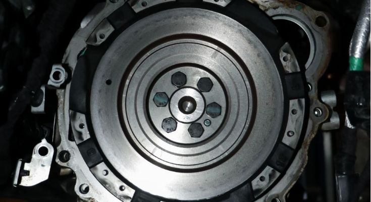
A car flywheel might just look like a simple metal disc at first glance, but it actually plays a crucial role in keeping an engine running smoothly. When we start working on engine parts, we discover that many of the performance issues are caused by the flywheel. Now, let us see how does a car flywheel work.
A car flywheel refers to a circular plate-like part that attaches to the engine crankshaft. In terms of engine activity, a flywheel serves to control rotation at low-rpm and give you better performance as well as improve your drive by decreasing the likelihood of stalling out.
To understand how the flywheel connects with other vehicle systems, see our guides on wheel and tire, car drive shaft, and automotive steering system.
A flywheel is used to ensure the smooth operation of an engine by regulating speed and providing a steady output of power. Its principle of operation is based on the concept of rotational inertia, which means that its mass tends not to change its velocity. This means that, since it is connected to the crankshaft, it spins with the engine and accumulates energy from combustion.
This energy is used for supplying continuous power between engine impulses. A car’s flywheel acts as a vibration absorber, helping minimize the risk of engine stalling. It assists engine starting by engaging its ring gear when the starter motor is engaged. From our experience in machining and balancing, just a few grams of misalignment can be enough to cause vibrations at high RPM.
The energy is stored in the flywheel in the form of rotational energy due to the acceleration caused by combustion in the engine. The energy is then used during power strokes to ensure the engine runs smoothly.
Another factor that we consider while choosing the flywheel is its mass. We use heavier flywheels since they store more energy, whereas lighter flywheels are more responsive to accelerate faster, but cause more vibration.

Now, let’s break down the key functions of a flywheel.
The use of the car flywheel is made to balance uneven forces that occur in the cylinders during the combustion process. The flywheel increases rotational inertia, thus minimizing vibrations.
We conserve additional kinetic energy during the power stroke and use it in the non-power stroke. This minimizes the loss of engine speed during the cycles and increases efficiency at low RPM and idle conditions.
Flywheels serve as a friction surface for clutch discs in manual gearboxes. Flywheels provide a means to facilitate the smooth transfer of torque as well as the controlled and gradual engagement of the clutch. They also allow heat to be distributed more evenly.
We depend on it to even out the torque pulses produced by combustion. It helps reduce the variation of RPM between firing events, thereby improving the refinement of the engine and minimizing the delay when the throttle is opened.
The flywheel is used to keep the crankshaft moving in a continuous fashion throughout the intake, compression, and exhaust strokes. This ensures that the crankshaft does not slow down before the next combustion stroke.
The flywheel is used to minimize the stress imposed by rapid acceleration on the drive train. It ensures that there is minimal stress experienced by gears, constant velocity joints, and shafts.

Depending on the engine, transmission, and driving requirements, we employ various flywheel designs. Each design maintains a different balance among inertia, dampening, weight, and longevity.
A Single-Mass Flywheel (SMF) is a single solid disk, often composed of cast iron or steel, with no internal dampening components. Most passenger cars have a weight range of 6 to 12 kg. It’s relatively inexpensive, long-lasting, and simple to manufacture due to its straightforward design.
When used under normal conditions, it can endure friction-induced temperatures of 300-400°C. We choose this design when we want the engine to react quickly while keeping the relationship to the transmission as direct as possible. What’s the downside? Without dampening, greater vibration spreads throughout the entire drivetrain.
In this situation, we’ll divide the flywheel into two separate masses that are connected by springs and dampers. In most circumstances, its weight will range between 10 and 18 kg, depending on the torque range, which can range from 200 to 600 Nm or even more, particularly for diesel engines.
Its internal springs will help to mitigate the influence of vibrations, reducing them by up to 70-90%. We use DMFs in modern automobiles where smooth functioning and low noise levels are crucial. The disadvantages include higher expenditures and more complicated wear in the long run.
This type of flywheel is manufactured from a single piece of alloyed steel, usually 4140 or 4340. As a result, this flywheel can withstand tensile forces higher than 850 MPa without being deformed.
In addition, this flywheel operates efficiently at elevated engine speeds, exceeding 7,000 RPM. We usually use Billet flywheels for high performance or high duty cycles.
To improve engine performance, we reduce the flywheel’s weight. This type of flywheel is usually manufactured from chromoly steel or aluminum, with an additional steel friction-surface insert.
The flywheel may weigh only 3–6 kilograms, which will decrease its inertia by 20–50% in comparison with ordinary flywheels. It is used when it is important to increase acceleration. However, such a flywheel will be rougher, especially at low speeds.
Flexplates replace conventional flywheels in automobiles equipped with automatic transmissions. It is made of a thin steel plate (about 2-4 mm thick) and weighs 2-5 kilograms. Flex plates connect the crankshaft and torque converter.
They have some flexibility to tolerate small misalignment and vibration, and they do not retain as much rotational energy as a traditional flywheel, but they serve a similar purpose of connecting the engine to the torque converter in an automatic transmission system.
In this configuration, the clutch has a dampening effect, which may be provided either by the flywheel or by the sprung hub. In this case, the shock load is absorbed using coil springs inside the clutch.
This way, impact loads will not be transmitted to the transmission, increasing its lifespan. Such a design is applied when we need better clutch dampening.

The car flywheel can be divided into multiple elements, with each playing an important role in energy storage, engine balance, and starter system interaction.
The flywheel cover serves as primary protection. It wraps the entire assembly, guarding it from dirt, dust, grease, and stress. It is designed to provide and enhance durability due to the engine’s continual vibrations.
We incorporate the main body or disc into our design as the flywheel’s essential structure. The main reason we do it in this manner is that the flywheel’s disk contains the majority of the energy stored. It also stabilizes the engine’s speed.
We consider our outer ring to be the heaviest component in the flywheel’s outer section. It ensures a greater moment of inertia, allowing the engine to operate more smoothly. It also contains the teeth of the ring gear for engine starting.
We provide mounting holes in the design of the car flywheel so that it can be attached securely to the crankshaft.
The ring gear is another component incorporated in the car flywheel design, being designed as a toothed steel ring that can connect with the starter motor’s pinion gear to start the engine.
The connection between the flywheel and the crankshaft is established by means of the flange surface. The flange area is precisely machined to ensure that torque transfer from the engine to the flywheel occurs smoothly without any misalignment and vibrations.
These are used to bear the weight during rotation. Axial bearings provide protection against any thrust forces, while radial bearings protect from side loads.

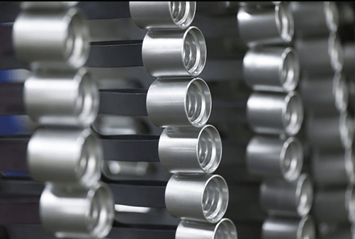
Material Selection: We use high-quality materials to endure engine loads. Lightweight materials may be required in performance applications to obtain greater responsiveness and speed.
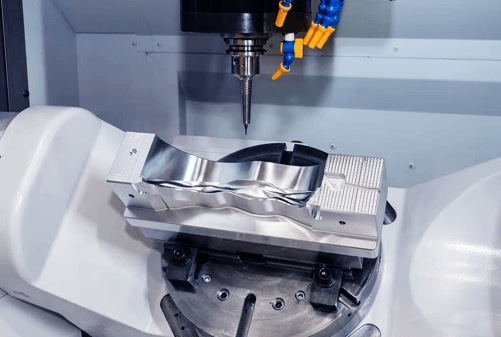
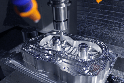
Precision and Accuracy: Maintaining balance in the flywheel needs a high level of precision. We use CNC machining to achieve accuracy, while die casting and stamping are suitable for bulk manufacturing.
Surface Treatment Options: We apply heat treatments and coatings to enhance strength, durability, and heat-dissipation capacity.
Clutch Compatibility: The flywheel’s compatibility with the clutch system ensures efficient coupling.

Designers are increasingly resorting to lightweight materials such as carbon fiber composites and sophisticated alloys rather than standard cast iron. These materials help to reduce weight while simultaneously increasing rotational efficiency and energy storage capacity.
Magnetic bearing systems are increasingly being used in high-end flywheels to allow for more than 60,000 spins per minute. These technologies decrease frictional losses, increasing energy efficiency.
In an electric vehicle, we still consider that flywheels have a lot of potential. These can store energy generated during the braking process and immediately deliver it when the car accelerates. This can be combined with batteries, whose reaction time is slower. This combination would be very efficient in traffic jams and dense traffic situations.
Based on our experience with engine systems, we have found that the flywheel in cars is a vital part that is sometimes overlooked. Based on our engineering experience, we can certify that the flywheel is critical to the engine’s smooth operation and torque delivery.
The evolution of vehicle systems drives us to continually improve these components to meet modern requirements. For rapid prototype and dependable manufacturing support, contact AutoRapidProto.

Kim oversees engineering operations, including complex process planning, DFM reviews, and solving challenges associated with high-precision automotive components. He specializes in strict tolerance control and machining complex geometries essential for powertrain modules, suspension systems, and ADAS sensor housings. Outside of work, he enjoys the precision and strategy of playing snooker.
 Knowledges
 Knowledges
 Knowledges
 Knowledges
 Knowledges
 Knowledges


Fill out the form below and our team will get back to you promptly with a personalized quote tailored to your needs.